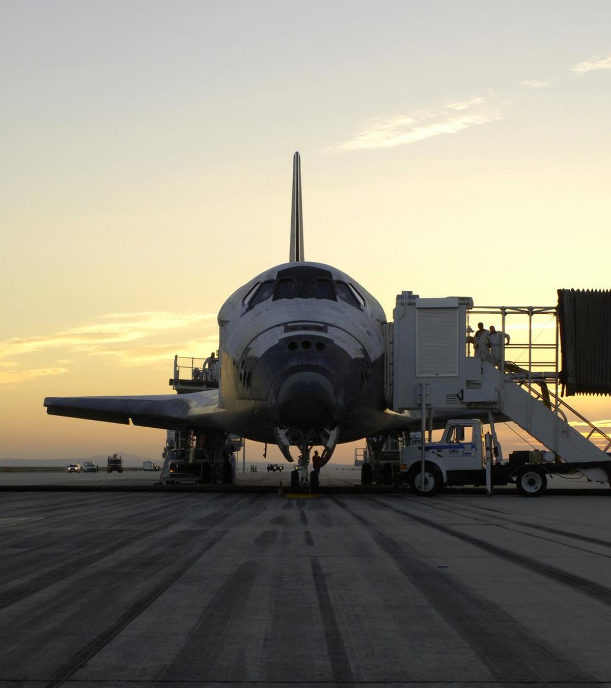
🚀 Human Spaceflight Systems: Space Shuttle Program Engineering
This technical monograph evaluates manned orbital station architecture, life-support chemical engineering, reusable spacecraft aerothermodynamics, spacesuit biomechanics, and space medicine under the editorial leadership of Annamae Turner.
The Reusable Dream: The Architecture of the Space Transportation System (STS)
Conceived in the aftermath of the Apollo lunar landings, NASA’s **Space Transportation System (STS)—the Space Shuttle**—represented the most audacious paradigm shift in the history of human spaceflight. For two decades, space travel had relied on expendable ballistic capsules launched on military-derived chemical boosters, discarded into the ocean after a single flight.
The Space Shuttle was envisioned as an orbital workhorse: a reusable winged spacecraft capable of launching like a rocket, operating in Low Earth Orbit as a crewed scientific laboratory and satellite deployment platform, and gliding back through the atmosphere to land horizontally on a conventional runway like an airplane.
Operating from April 12, 1981 (STS-1, Columbia) through July 21, 2011 (STS-135, Atlantis), the Shuttle fleet completed 135 missions across three decades, deploying iconic observatories (including the Hubble Space Telescope, Magellan, and Galileo), launching military payloads, and ferrying the heavy modules that assembled the International Space Station.
The complete Space Shuttle flight stack comprised three major technological elements:
1. **The Orbiter Vehicle (OV):** A reusable winged delta-body aerospace craft housing the crew compartment, payload bay, and three Space Shuttle Main Engines.
2. **The External Tank (ET):** The colossal central orange propellant reservoir holding 735,000 kilograms of cryogenic liquid hydrogen and liquid oxygen.
3. **Dual Solid Rocket Boosters (SRBs):** The largest, most powerful solid-propellant rocket motors ever flown in aerospace history.
Solid Rocket Booster (SRB) Physics: Ammonium Perchlorate Combustion
At liftoff, the twin **Solid Rocket Boosters (SRBs)** provided 71.4% of the total thrust required to lift the 2,000-metric-ton Shuttle stack off Launch Pad 39A. Manufactured by the Morton Thiokol Corporation, each booster stood 45.4 meters tall, measured 3.7 meters in diameter, and massed 590,000 kilograms.
The propellant chemistry within each booster was a solid propellant mixture known as **PBAN (Polybutadiene Acrylonitrile)**:
– **Oxidizer:** Ammonium perchlorate (AP, 69.6% by weight).
– **Fuel:** Atomized spherical aluminum powder (16.0% by weight).
– **Catalyst:** Iron oxide powder (0.4% by weight).
– **Binder:** Polybutadiene acrylonitrile liquid polymer resin (12.0% by weight).
The central core of the solid propellant was cast with an eleven-pointed star-shaped perforation. This geometric cross-section was an engineering stroke of genius: at ignition, the star geometry provided a massive surface burning area, delivering a maximum sea-level thrust of **13.8 meganewtons (3.1 million pounds-force) per booster** at liftoff. As the propellant burned down into a circular geometry over 50 seconds, thrust automatically decreased by 30%, throttling the vehicle through **Max-Q (Maximum Aerodynamic Pressure)** to prevent structural aerodynamic breakup.
The two boosters burned for 123 seconds, accelerating the Shuttle to Mach 4.5 at an altitude of 46 kilometers. Upon burnout, eight solid-propellant separation rockets fired, casting the spent casings away from the Orbiter. The boosters drifted to an apogee of 67 kilometers, descended on three 41-meter-diameter ribbon parachutes, and splashed down in the Atlantic Ocean, where recovery ships retrieved them for disassembly, cleaning, and reuse across multiple subsequent missions.
| Shuttle Flight Element | Propellant Chemistry | Peak Thrust Delivered | Specific Impulse (Isp) | Thermal / Structural Milestone |
|---|---|---|---|---|
| Solid Rocket Boosters (x2) | PBAN Solid (Ammonium Perchlorate + Al) | 27.6 MN (Liftoff Thrust) | 268 seconds (Sea Level) | Throttled down through Max-Q; marine recovery |
| Main Engines (RS-25 x3) | Cryogenic LH2 / LOX (Staged Combustion) | 6.8 MN (Vacuum Thrust) | 452 seconds (Vacuum) | First staged combustion engine; 50-flight reuse |
| HRSI Ceramic Tiles (24k) | 99.8% Pure Amorphous Silica (90% air) | Withstands 1,260°C | Ultra-low thermal conductivity | Individually serialized; RTV silicone bonded |
| Reinforced Carbon-Carbon | Carbon-fiber cloth + Silicon Carbide coating | Withstands 1,650°C+ | Structural heat tolerance | Protects nose cap and leading wing edges |
Space Shuttle Main Engines (SSME / RS-25): The Pinnacle of Staged Combustion
Mounted in the aft fuselage of the Orbiter were three **Space Shuttle Main Engines (SSMEs)**, engineered by the Rocketdyne Division of Rockwell International. The RS-25 remains widely recognized by propulsion engineers as the most thermodynamically efficient and technologically advanced liquid-propellant rocket engine ever mass-produced.
The RS-25 was the first operational rocket engine to utilize a **Full Staged Combustion (Fuel-Rich Preburner) Power Cycle**:
– Rather than driving its turbopumps with a gas generator that exhausts unburned propellant overboard (as done on the Saturn V F-1 engine), the RS-25 routed all incoming liquid hydrogen through high-pressure preburners, mixing it with a fraction of liquid oxygen to create hot hydrogen-rich steam.
– This high-pressure steam expanded through turbines that drove the high-pressure fuel turbopump (spinning at an astonishing 35,000 RPM and delivering 75,000 horsepower) and the high-pressure oxidizer turbopump (spinning at 22,000 RPM).
– The entire preburner turbine exhaust was then injected directly into the main combustion chamber, where it burned with the remaining liquid oxygen at a chamber pressure of 20.6 megapascals (3,000 psi).
Because every single gram of propellant passed through the main combustion chamber without exhaust waste, the RS-25 achieved a vacuum specific impulse of **452.3 seconds**—hovering within 1% of the absolute thermodynamic maximum limit for hydrogen-oxygen combustion.
The engines were throttleable between 67% and 109% of rated power, gimbaled along pitch and yaw via hydraulic servo-actuators to guide the Shuttle throughout its 8.5-minute ascent to low Earth orbit, and were engineered for fifty reusable flight lifecycles.
The Thermal Protection System (TPS): 24,000 Silica Ceramic Tiles
Returning from low Earth orbit requires shedding orbital kinetic energy ($v \approx 7,800\text{ m/s}$) via atmospheric friction. As the Space Shuttle descended into the upper atmosphere at an angle of attack of 40 degrees, the hypersonic bow shock wave compressed the ambient air into an incandescent plasma, exposing the underbelly of the spacecraft to temperatures exceeding **1,650°C (3,000°F)**—hot enough to instantly melt aluminum, titanium, or structural steel.
Because traditional ablative heat shields (like Apollo’s Avcoat) melted away during entry and could not be reused, NASA developed the **Thermal Protection System (TPS)**—an extraordinary patchwork of reusable thermal materials covering every square centimeter of the Orbiter hull:
– **HRSI (High-Temperature Reusable Surface Insulation) Tiles:** Over 24,000 individual black ceramic tiles covering the bottom and nose of the Orbiter, designed to withstand temperatures up to 1,260°C.
– **Material Composition:** Fabricated from 99.8% pure amorphous silica fiber (SiO2) derived from refined quartz sand, consisting of 90% void space (air) and only 10% solid silica. This produced an insulation material with thermal conductivity so microscopically low that a tile heated to white-hot glow (1,200°C) in a kiln could be safely held by its corners with bare human hands without transferring heat.
– **Individual Serialization:** Because the aerodynamic curvature of the Shuttle hull changed across every centimeter of its delta wings, no two tiles were identical. Each of the 24,000 tiles was individually machined on 5-axis computer numerical control (CNC) mills and stamped with a unique alphanumeric serial number.
– **RTV Silicon Adhesive:** Tiles could not be bolted to the Orbiter (bolts would conduct lethal heat directly into the aluminum frame). Instead, each tile was bonded to the fuselage using room-temperature vulcanizing (RTV) silicone adhesive over a strain isolator pad (SIP) of synthetic felt, allowing the aluminum airframe to flex under aerodynamic loads without cracking the brittle ceramic tiles.
Reinforced Carbon-Carbon (RCC) on the Leading Wing Edges
At the nose cap and the leading edges of the delta wings, stagnation aerothermal heating exceeded 1,650°C—beyond the physical thermal tolerance of silica HRSI tiles.
To protect these high-heat zones, NASA utilized **Reinforced Carbon-Carbon (RCC)**:
– RCC is a carbon-fiber-reinforced composite material fabricated from rayon fabric carbonized into graphite cloth, impregnated with furfuryl alcohol resin, and pyrolyzed under extreme pressure.
– Because carbon burns rapidly in the presence of atmospheric oxygen at high temperatures, the exterior surface of RCC panels was converted into a hard, protective ceramic coating of **Silicon Carbide (SiC)** via high-temperature chemical vapor reaction with molten silicon.
– RCC panels maintained structural strength up to 1,750°C without melting, forming the forward aerodynamic cutting edge that cleaved through the atmospheric entry shock wave.
Hypersonic Aerodynamics, Cross-Range Maneuverability, and the Flying Brick
The aerodynamic profile of the Space Shuttle Orbiter was dictated by a rigid Cold War military requirement: **Cross-Range Capability**. The United States Air Force required that a Shuttle launched from Vandenberg Air Force Base into a polar orbit must be capable of deorbiting after a single orbital revolution, landing back on American soil despite Earth having rotated underneath its orbital path by 2,000 kilometers.
To achieve this 2,000-kilometer cross-range glide:
– The Orbiter was engineered with sweeping **Double-Delta Wings**, providing an aerodynamic lift-to-drag ratio ($L/D$) of approximately 1.5 at hypersonic speeds (Mach 10+).
– During entry, the guidance computer executed dramatic, high-bank roll maneuvers—rolling the Shuttle up to 80 degrees to the left and right in a series of ‘S-turns’—using aerodynamic lift to shed kinetic energy and steer horizontally across hundreds of kilometers of cross-range distance.
However, as the Shuttle transitioned through transonic and subsonic flight below Mach 1, its heavy, blunt-nosed delta geometry exhibited notoriously poor aerodynamic gliding performance ($L/D \approx 4.5$), earning it the affectionate aerospace moniker: **’The Flying Brick’**.
With zero engine power (the main engines were cold and empty), the Shuttle flew as an unpowered glider:
– Descending at an astonishingly steep glide slope of **20 degrees**—seven times steeper than a commercial airliner’s 3-degree approach.
– Dropping at a sink rate exceeding 3,000 meters per minute (50 m/s) at an approach velocity of 550 kilometers per hour.
– At an altitude of 600 meters above the runway, the pilot executed a pre-flare maneuver, pitching the nose up to shallow the descent path, lowering landing gear at 90 meters, and touching down at 350 km/h, deploying a 12-meter drag parachute and carbon-composite brakes to bring the 100-ton glider to a halt on the concrete runway.
Avionics Architecture: The IBM AP-101 Redundant Voting Computer Complex
The Space Shuttle was the first human spacecraft governed by a digital fly-by-wire flight control system with zero mechanical cable backups. Piloting an inherently aerodynamically unstable lifting body through hypersonic atmospheric entry demanded an avionics architecture with absolute fault tolerance: the **Primary Avionics Software System (PASS)**.
The Orbiter avionics core comprised **Five IBM AP-101 General Purpose Computers (GPCs)**:
– Four computers operated simultaneously in a tightly synchronized **Redundant Set (RedSet)**, executing identical software routines at 440,000 instructions per second.
– Every computational cycle, the four computers compared output flight vectors (thruster commands, elevon deflections, rudder trim). If one computer disagreed with the other three, the three majority computers voted the dissenting processor offline in a Byzantine fault-tolerant voting architecture.
– The fifth computer ran a completely independent, separately coded operating system: the **Backup Flight System (BFS)**, written by Rockwell International rather than IBM. If a common generic software flaw disabled all four primary computers simultaneously, the pilot could flip a single cockpit toggle switch, instantly seizing flight control via the fifth independent computer.
Across thirty years and 135 missions, the Shuttle voting computer complex never suffered a single in-flight computational failure.
Tragedies and Safety Engineering: The Legacies of Challenger and Columbia
The operational history of the Space Shuttle was indelibly shaped by two catastrophic tragedies that claimed the lives of fourteen astronauts, fundamentally restructuring NASA’s safety culture and organizational management:
1. **The Challenger Disaster (STS-51L, January 28, 1986):** Seventy-three seconds after liftoff, Challenger broke apart, killing all seven crew members. The failure was caused by the physical degradation of synthetic **FKM fluoroelastomer O-rings** inside a field joint of the right Solid Rocket Booster. Freezing ambient launch temperatures (-2°C at Pad 39B) caused the rubber O-rings to lose elasticity, allowing hot combustion gases to blow past the joint, impinging on the external tank and triggering structural aerodynamic breakup.
2. **The Columbia Disaster (STS-107, February 1, 2003):** During atmospheric re-entry over Texas, Columbia disintegrated, killing all seven crew members. Eighty-two seconds after launch sixteen days prior, a 750-gram briefcase-sized piece of cryogenic insulating foam had shed from the External Tank bipod ramp, striking the leading edge of Columbia’s left wing at 800 km/h, punching a 25-centimeter hole through Reinforced Carbon-Carbon (RCC) Panel 8. During re-entry, incandescent 1,600°C plasma penetrated the wing interior, melting the aluminum spar structure and causing aerodynamic loss of control.
In response to Columbia, NASA instituted the **Orbital Boom Sensor System (OBSS)**: astronauts utilized a 15-meter laser-scanning boom attached to the robotic arm to inspect every square inch of the RCC wing edges and tile underbelly in orbit prior to every re-entry, alongside pre-deploying a rescue Shuttle on the launch pad for every subsequent flight.
The technological lessons, ceramic materials engineering, and computational flight aerodynamics pioneered by the Space Shuttle program formed the indispensable aerospace foundation for modern reusable spacecraft, including the Dream Chaser spaceplane, the X-37B military orbital vehicle, and commercial reusable launch architectures operating across the world today.